Exercise 8 – RS Part 2 – Optional task
Explore imagery – Spatial resolution
By Madeline Wrable and Delphine Khanna*
Outline (optional)
| Task 3 – (Optional) Change the spatial resolution of an image – Learn about changing spatial resolution and resampling imagery to a larger cell size. | 10 minutes (Optional) |
Task 3 (Optional) – Change the spatial resolution of an image
Next, you’ll learn about changing the resolution of an image and become familiar with the concept of resampling. Then, you’ll resample imagery yourself and compare the original imagery layer and the resampled output.
A – Learn about changing the spatial resolution and resampling
When you receive some imagery or another type of raster data, you can use it with its original spatial resolution. However, in some cases, you may want to change it.
- If the features of interest for your project don’t require a very high spatial resolution, and you want to minimize storage and processing time, you can increase the cell size.
- If several raster layers in your project have different spatial resolutions, the best practice for analysis is to change the spatial resolution of some of the layers so that they all have the same cell size.

Changing the spatial resolution is achieved through a process called resampling. Resampling is used any time a raster grid needs to be transformed. Another example of grid transformation is if you need to reproject a raster (to learn more about projections, see the Choose the right projection tutorial). There are also various geoprocessing tools that use resampling, such as the Surface toolset.

To apply resampling, you must choose a method to compute the value of each cell in the output raster. The following are three examples of resampling methods that can be applied to imagery:
- Nearest neighbor—Each cell in the output raster will take the exact value of the closest corresponding cell in the original raster.
- Bilinear interpolation—The value of a cell in the output raster is computed by averaging the corresponding four neighboring cells in the original raster, yielding a smoother output.
- Cubic convolution—The value of a cell in the output raster is computed by averaging the corresponding 16 neighboring cells in the original raster.

Note: Learn more about resampling in Cell size and resampling in analysis.
B – Resample imagery to a larger cell size
Next, you’ll learn how to resample imagery to change its cell size. You plan to use a 3-meter PlanetScope image for your project but know that other raster layers in the same project have a 10-meter cell size. You’ll resample the PlanetScope image to match the 10-meter resolution. First, you’ll switch to the third map of the project.
1- Click the Resampling tab.

This map contains the PlanetScope_01012023_3m image, similar to the one you saw earlier in the workflow. To resample the image, you’ll use the Resample geoprocessing tool.
2- On the ribbon, on the View tab, in the Windows group, click Geoprocessing.

The Geoprocessing pane appears.
3- In the Geoprocessing pane, in the search box, type Resample. In the list of results, click the Resample tool to open it.
This tool resides in the Data Management toolbox.

4- In the Resample tool, choose the following parameter values:
- For Input Raster, choose PlanetScope_01012023_3m.
- For Output Raster Dataset, type PlanetScope_01012023_10m.

5- Under Output Cell Size, the X and Y fields currently show the resolution of your input image: about 3 meters. You’ll replace it with your target value.
Under Output Cell Size, for X and Y, type 10.

NOTE: When resampling imagery, you often go to a larger cell size, as is the case in this workflow.You should exercise caution when resampling to a smaller cell size. It is important to understand that no new data will be created. Specifying a cell size of 50 meters when the input image has a resolution of 100 meters will create an output raster with a cell size of 50 meters; however, the accuracy will still remain 100 meters.
6- For Resampling Technique, choose Bilinear.

The resampling techniques that you learned about earlier are available: Nearest (Neighbor), Bilinear, and Cubic. All three can be used for imagery. Bilinear will produce a smoother result.There is another option, Majority, which is usually not used for imagery. You can learn more about that option in the Resample documentation.
NOTE: There is another type of raster named thematic (or categorical, or also discrete) that should only be resampled with the Nearest or Majority methods because it is important to preserve the original cell values. Learn more about the different types of raster data.
7- In the Resample tool pane, click the Environments tab and locate the Output Coordinates section.

If you wanted to reproject the image instead of or in addition to changing the cell size, this is where you would specify the target coordinate system. In this workflow, you won’t reproject, so you’ll leave these parameters blank.
8- Click Run. After a few moments, the new PlanetScope_01012023_10m image appears on the map.

It looks darker than the original image because it uses a default rendering. You’ll change its display settings to match the original.
NOTE: Learn more about imagery appearance options.
9- In the Contents pane, right-click PlanetScope_01012023_10m and choose Symbology.

10- In the Symbology pane, click the options button and choose Import from layer.

11- Under Apply Symbology From Layer, choose the following parameter values:
- For Input Layer, confirm that PlanetScope_01012023_10m is selected.
- For Symbology Layer, choose PlanetScope_01012023_3m.

12- Click Run. The resampled image updates to show a rendering similar to the original image.
C- Compare original and resampled imagery
Next, you’ll compare the original and resampled layers using the Swipe tool.
1- In the Contents pane, ensure that the PlanetScope_01012023_10m layer is selected.

2- On the ribbon, on the Raster Layer tab, in the Compare group, click Swipe.

3- On the map, drag from top to bottom to peel off the PlanetScope_01012023_10m layer and reveal the PlanetScope_01012023_3m layer under it.

At this scale, you see almost no difference between the two images. In both cases, you can distinguish the larger features such as the regreening project area and the numerous agricultural fields. You’ll zoom in to a greater level of detail.
4- On the ribbon, on the Map tab, in the Navigate group, click Bookmarks and choose the Roads and fields bookmark.

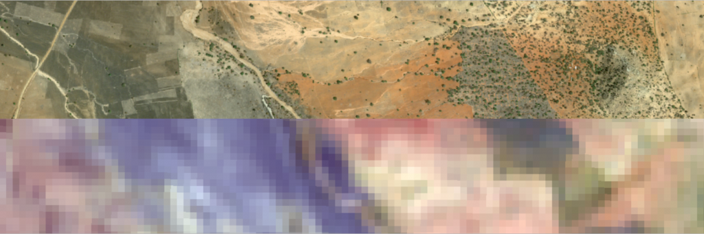
5- Drag to swipe from top to bottom with the swipe pointer.

At this scale, the resampled layer looks more blocky than the original image because its cells are larger. Finally, you’ll zoom in further to see individual cells.
6- On the ribbon, on the Map tab, click Bookmarks and choose the Cells bookmark.

Drag to swipe and compare the two layers.

You can clearly see that the cells from the resampled layers are about three times wider than those of the original layer.
7- When you are finished exploring, on the ribbon, on the Map tab, in the Navigate group, click the Explore button to close the swipe mode.

In this part of the tutorial, you learned that you can change the spatial resolution of an image. You learned about the concept of resampling and became familiar with several resampling methods. Then, you resampled an image to a greater cell size and compared original input and resampled output.
Go to start page Mapping & Spatial Analysis
Source:
This tutorial was originally developed by the Esri Tutorials Team.
You can find the official maintained version at this location
https://learn.arcgis.com/en/projects/explore-imagery-spatial-resolution/
You can find other tutorials in the tutorial gallery [https://learn.arcgis.com/en/gallery/].