- Design the basic shape of the wings
- Test the proper length of the wings (with the help of dancers)
- Experiment with the solidity of the wires
- Study how tilt sensors work
- Determine SquareWear vs CPB
After confirming all the plans and getting all the materials in the first week (Shein was really slow! But I’m very happy with the texture of all the cloth and stuff), I decided to start by making a rough shape of the wings as planned.
First, I needed to figure out how big the wings would actually be. This hardware should depend on a comfortable arm’s length distance for the dancer, as well as being aesthetically pleasing enough and ergonomic. I asked Alice, who is a dance minor, about this and tested the approximate length – the right distance should be longer than one arm, since the wings start higher than the shoulder joint. I also searched Pinterest for artworks that fit my design vision: they all had a certain dark or dangerous mystical element but at the same time were elegant and glamorous, so the lines were very stiff.
@DreamValley humanoid.
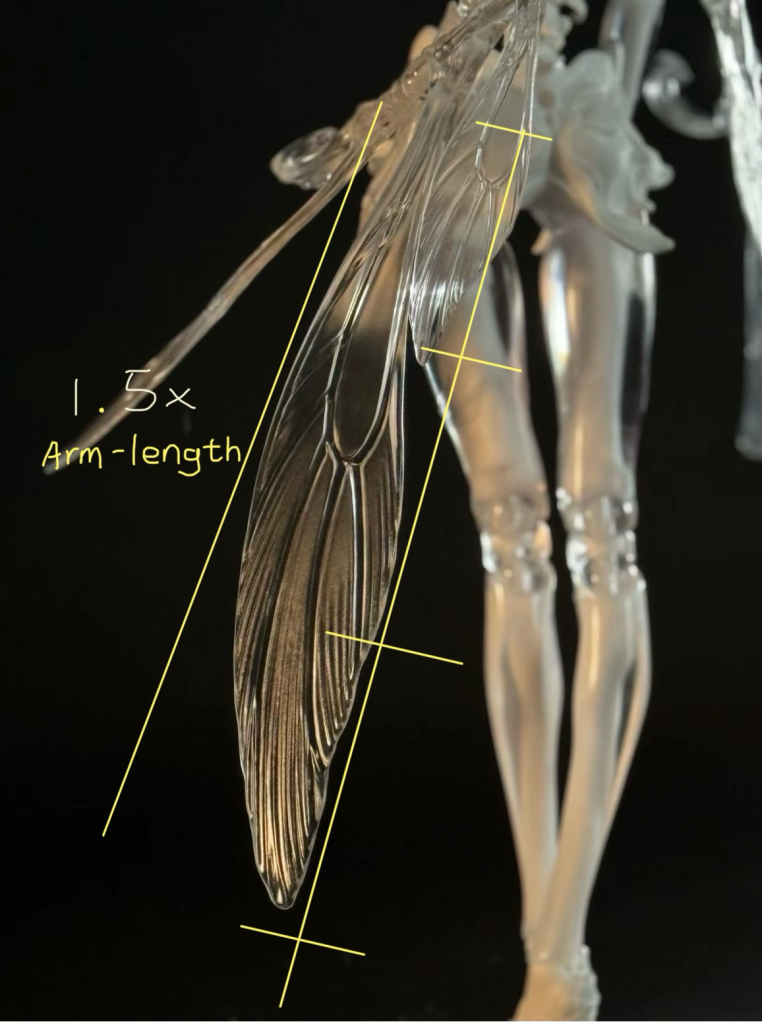
@Sainker.
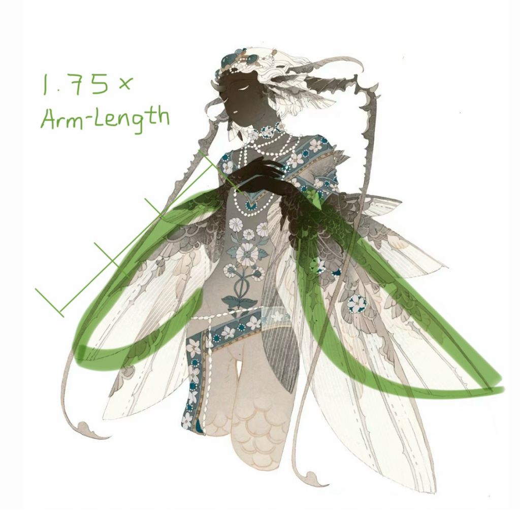
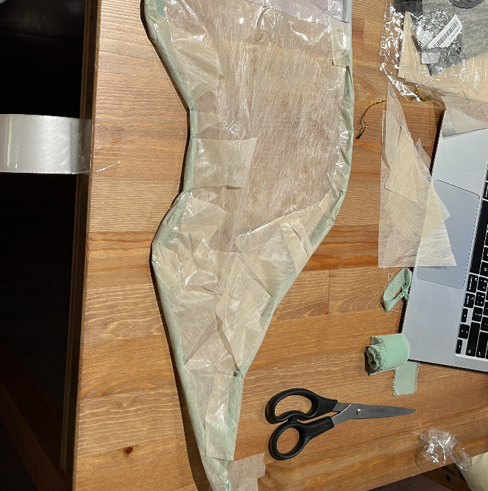
So I finally decided to make large wings with an arm span of about 1.2 times that of an adult female (average height of about 160cm). Also I wanted the wings to be soft and have some sci-fi elements, so they had to have some curvature and also have a stiff profile. I then tightened the wire bundles and ran them through the approximate shape of the wings, and then tied on green fabric for a secondary shape. The result was a great skeleton that could be shaped but was also strong in its own right!
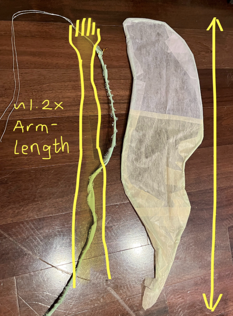
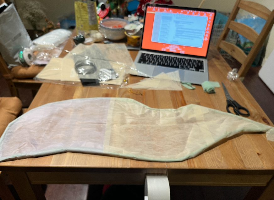
I then tested the effect of different colours of flower wrapping paper as the basic layer above the wings. I wanted to go the whole hog with a soft gradient like my sketch, but with limited materials I had to be flexible and shift my thinking. I only covered the ends with a large purple colour on both sides of the wings and then used yellow for the rest. On the transitions I put small irregular pieces so that it has more of a scale effect. It didn’t turn out as well as I had initially planned, but I’m still very happy with this final base colour. With effective cost control we need cognitive flexibility to move forward with the project.
When I wanted to identify how to incorporate the element of tilt sensors, I searched the web for the keywords “tilt sensor” and “LED”. Then a miracle happened: I was surprised to find a results blog from our Idesign course member, Madeline Ketley, from more than a decade ago! I knew that some of my classmates had done projects combining tilt sensors and lighting before me, but I never thought it could be so far away and yet so dear to me. When I clicked in, I found a familiar pattern of work: looking for TA, thinking alone, and discussing with Audrey. A sense of belonging suddenly came over me all at once. Through this thread, I understood more practically the whole picture of this project, including the techniques used and the difficulties I might encounter.
In my excitement, I even contacted Madeline Ketley via email – and another miracle happened! Madeline was also supportive and gave me some advice (one of which was that SqaureWear was difficult to use, which was an understatement). A moment of unrivalled happiness and pride overwhelmed me. I have never felt so connected and belonging from a classroom community, but it was happening right in front of my eyes at the moment.
Specifically, Madeline used a tilt sensor sewn into the waist of her ballet skirt to collect changes in the relative position of the dancer’s waist and reflect it in the light. Unlike me, her project serves more of a pedagogical purpose, i.e., the accuracy of the movement can be judged by the changes in light.
In this ancient project, she used a lot of parts that we are not familiar with for testing: bread cubes, bulky batteries, and LEDs that don’t work very well, as well as the all-important SquareWear. I compared the SqaureWear to the Arduino Circuit Playground Board (CPB) that we used, and I found that they are basically the same size (of course, at that time, the SquareWear was significantly smaller and lighter, thanks to the development of the times), and at the same time, they are basically the same size. The SquareWear’s signal contact may not be as stable, and the code used is not quite the same. It also requires an additional tilt sensor, but the CPB is a pleasantly surprising collection of features. So in order to complete the project more efficiently, I decided to use a combination of CPB and LED to complete the project.

I was able to understand how the tilt sensor determines its relative position in 3D space by comparing her presentation with the code examples I found on the internet. To do this, three directional values need to be established:
– X = rotate around the centre
– Y = tilt forward/backward
– Z = tilt left/right
So, in Madeline’s mindset, she tried to build this system (of course, she succeeded and it worked great!)
If you rotate on the x-axis, the lightbar is red.
If you tilt it on the y-axis, the lightbar is blue.
If tilted on the z-axis, the lightbar is green.
If not tilted on the x-, y- or z-axis, the rainbow cycle begins.
The exact technical principle is that the tilt sensor will read a certain range of values from the x, y and z axes. The code compares x to y and z and then y to x and z to determine which is greater and lights the LED chain that way.
With Madeline’s extremely helpful overview of the general direction, I quickly figured out that there are a myriad of wonderful variations that can occur between x,y,z. But I wanted to make the changes in lighting more visible on stage in echo with the action, so I decided to make a different lighting choreography.
After some thought, I decided to change the logic of the lighting changes. I changed the flashing lights to a combination of three colours (R,G,B) to create a coloured glow. The light flashes uniformly at the same frequency across the entire strip, and if there are different levels of changes in the x,y,z directions, the colours of the lights will change together. As a result, the light will have a softer transition and the overall appearance will be more colourful.
Some of the programming logic (I call them conversions between human language and pseudo-code) is listed below. Thanks to assistant teacher Kalki for his help! We sorted out the ideas together.
If the acceleration value in the x-direction is high (positive), add the red element
If scaled_ax is ________, increase the R value
If the acceleration value in the x-direction is low (negative), decrease the red element
If scaled_ax is ________, decrease the R value
If the acceleration value in the y-direction is high (positive), increase the blue element
If scaled_ay is ________, increase the B value
If the acceleration value in the y-direction is low (negative), decrease the blue element
If scaled_ay is ________, decrease the B value
If the acceleration value in the z direction is high (positive), increase the green element
If scaled_az is ________, increase the G value
If the acceleration value in the z-direction is low (negative), decrease the green element
If scaled_az is ________, decrease G value
If the acceleration in the x-, y- and z-direction is zero, do nothing
If scaled_ax, scaled_ay and scaled_az are zero, do nothing
I don’t have a way to test the lights right away, but Kalki is very much in favour of me completing the base frame first. This is an important part of self-regulation, as an ordered logical structure can better help us get a handle on exactly what kind of code we need to knock out. Breaking the code down into specific parts that need to be done when you have a specific plan is where “pseudo-code” comes in handy.
In addition, I noticed in the Madeline logs that there are reminders about thresholds in all three directions. This is invaluable information, because if the value in one direction keeps moving very slightly when the wings are actually applied, then we need to artificially amplify its presence, otherwise the light will keep missing a colour tone overall. I need to test the lights to find a comfortable value for the delay, or artificially make some adjustments to the numbers in some directions that have been at 0. According to Madeline’s description, the tilt sensor theoretically puts the value between 0 and 179, so I’ll be isometrically amplifying the value to project the data onto the RGB’s from 0 to 255 (if this theory is accurate).
