
Project Aim
Develop a noise detector that buzzes and lights up when the sound levels reach above a certain level acceptable in the tranquility room in the dining hall.
Team Members
Sulagna Saha, Yu Wati Nyi, Mumtaz Fatima
Documentation of Our Build Process
- Collect the required components from the Arduino Kit. The required components were: Arduino Uno kit, Breadboard, Buzzer, LED Light, Sound Sensor
- Connect the Arduino Uno to the breadboard and make the necessary connections with the LED bulb, Buzzer, and Sound Sensor
- Modify the code and add the functionality to activate buzzer whenever the sound sensor detects a value, it saves the value, finds the peak value, uses this value of the detected sound to convert it into volts.
- Cardboard box:
- Cut cardboard to create a box with 2 open lateral ends.
- Make 3 holes to add the components. One hole on the top to attach the sound sensor and 2 holes on the side to attach the LED and the buzzer
- Test the connections and view the serial monitor to check whether the code works as intended
- Finally attach the breadboard to the bottom of the cardboard box and cover the 2 open ends.
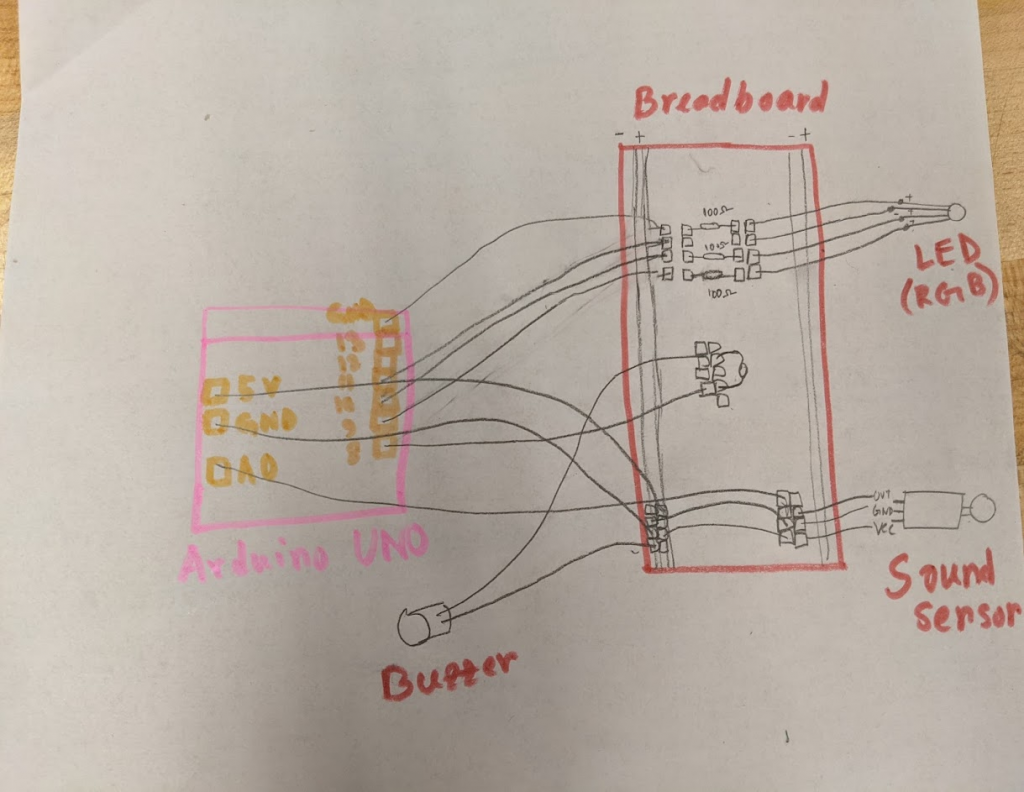
Circuit Diagram
Code
/*
 MAX4466 (adafruit mic)

 Written by Shani Mensing, edited by Audrey St. John
Modified by Yu Wati Nyi, Mumtaz Fatima, Sulagna Saha

 Circuit: microphone VCC connected to 3.3V, OUT to analog input A0
 */

// hook up the out of the mic to analog input A0
int MIC_IN = A0;

// Sample window width in milliseconds (50 ms = 20Hz)
int sampleWindow = 50;
int red_light_pin= 11;
int green_light_pin = 10;
int blue_light_pin = 9;
Int buzzer_pin = 8;

/**
 * Initialization code
 **/
void setup()
{
   // open serial port and set data rates to 9600 bps (bits-per-second)
   // this lets us communicate to/from the arduino
   Serial.begin(9600);

   pinMode( MIC_IN, INPUT );
   pinMode(red_light_pin, OUTPUT);
   pinMode(green_light_pin, OUTPUT);
   pinMode(blue_light_pin, OUTPUT);
   pinMode(buzzer_pin, OUTPUT);
}

/**
 * Main program loop happens constantly.
 **/
void loop()
{
    // read the analog sensor as volts
    double soundSensed = sampleSoundPeak();

    // convert to volts
    double volts = (soundSensed * 3) / 1024;
    if(volts<1){
      RGB_color(0, 255, 0); // Green
      delay(1000);
    }
    else{
      RGB_color(255, 0, 255); // Magenta
      delay(1000);
      tone(buzzer_pin, 1000); // Send 1KHz sound signal...
      delay(1000);        // ...for 1 sec
      noTone(buzzer_pin);     // Stop sound...
      delay(1000);
    }

    // print it out
    Serial.println(volts);
}

/////////////// Our own methods

/**
 * Sense biggest input difference are being input from the analog MIC sensor
 * over a certain "window" of time.
 * Values returned are in the range 0 - 1024.
 **/
double sampleSoundPeak()
{
    // record start time
    double startMillis = millis();

    // this will be the highest peak, so start it very small
    int signalMax = 0;

    // this will be the lowest peak, so start it very high
    int signalMin = 1024;

    // will hold the current value from the microphone
    int sample;

    // collect data for 50 ms
    while ( (millis() - startMillis) < sampleWindow )
    {
        // read a value from mic and record it into sample variable
        sample = analogRead( MIC_IN );

        // toss out spurious readings
        if (sample < 1024)
        {

            // if the current sample is larger than the max
             if (sample > signalMax)
             {
                   // this is the new max -- save it
                   signalMax = sample;
             }
             // otherwise, if the current sample is smaller than the min
             else if (sample < signalMin)
             {
                   // this is the new min -- save it
                   signalMin = sample;
             }
         }
     }

     // now that we've collected our data,
     // determine the peak-peak amplitude as max - min
     int peakDifference = signalMax - signalMin;

     // give it back to the caller of this method
     return peakDifference;
}
void RGB_color(int red_light_value, int green_light_value, int blue_light_value)
{
  analogWrite(red_light_pin, red_light_value);
  analogWrite(green_light_pin, green_light_value);
  analogWrite(blue_light_pin, blue_light_value);
}